小型遠心ブロワーでサージングが発生する原因は何ですか?また、エンジニアはどのようにして不安定な気流を防ぐことができますか?
August 31 , 2026小型遠心送風機は、電子機器、医療機器、家電製品、冷凍システム、バッテリー機器、充電機器、制御盤、換気システムなど、様々な小型機器に広く使用されています。これらの送風機は限られたスペースに設置されることが多いため、エンジニアは風量、静圧、騒音、消費電力、寸法、信頼性のバランスを取る必要に迫られることがよくあります。
多くの用途において、小型送風機の選定は一見簡単そうに見える。エンジニアは必要な風量と製品仕様書に記載されている最大風量を比較し、十分な容量を持つモデルを選択するだろう。しかし、送風機を機器システム全体に設置した後では、実際の風量性能は大きく異なる可能性がある。
理由は簡単だ。送風機は単独では作動しないからだ。
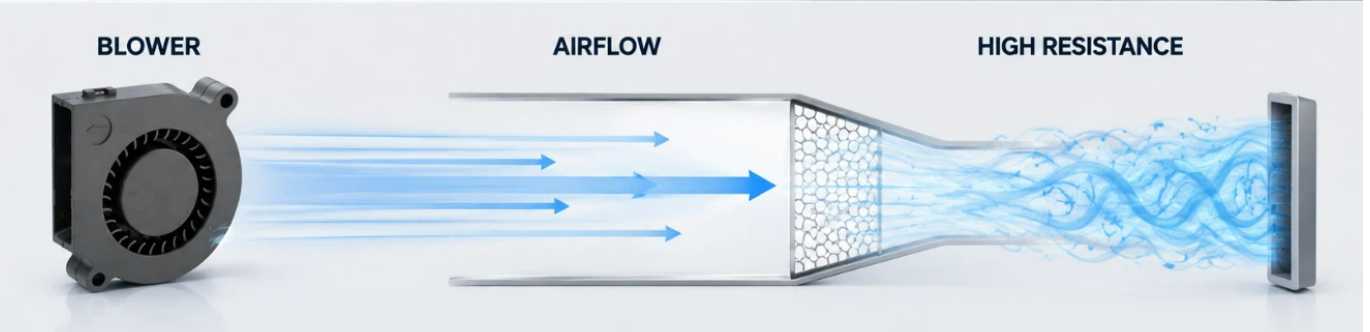
送風機は、エアダクト、フィルター、ヒートシンク、通気口、グリル、曲がり部、狭い通路、熱交換器、その他の部品によって生じる抵抗を克服しなければなりません。この抵抗が大きくなりすぎると、送風機の動作点が理想的な範囲から外れてしまいます。その結果、風量が大幅に減少したり、圧力が変動したり、異音や振動が発生したりする可能性があります。
状況によっては、送風機と接続された気流システムとの相互作用により、送風機のサージングや流量不安定性などと呼ばれる不安定な運転状態が発生する場合があります。
大型産業用遠心機の場合、サージは強い圧力と流量の振動を伴う深刻な空力現象となる可能性があります。一方、小型機器に使用される小型遠心ブロワーの場合、状況はそれほど深刻ではありません。エンジニアは、大型産業システムに見られるような深刻なサージ現象に遭遇する前に、高いシステム抵抗、著しい風量減少、圧力変動、脈動音、または不安定な風量といった問題に遭遇する可能性の方が高いでしょう。
小型送風機を備えた機器を設計する際には、この違いを理解することが重要です。
この記事では、小型遠心式ブロワーにおけるブロワーサージングの意味、過剰なシステム抵抗が不安定な気流を引き起こす理由、エンジニアが潜在的な問題を特定する方法、そして適切なブロワーの選定と気流経路の設計によってリスクを軽減する方法について説明します。
ブロワーのサージングとは何ですか?
ブロワーサージングとは、ブロワーによって発生する気流と圧力が比較的安定した状態を保つのではなく、変動する不安定な空力状態を指します。
この現象は、送風機の性能とシステム抵抗の関係に深く関係している。
遠心式ブロワーには必ず性能曲線があります。この曲線は通常、静圧の変化に伴う風量の変化を示しています。システム抵抗が低い場合、ブロワーは通常、比較的高い風量を供給できます。システム抵抗が増加すると、ブロワーはより高い圧力で動作する一方で、風量は減少します。
完全な機器システムにも、独自の抵抗特性がある。
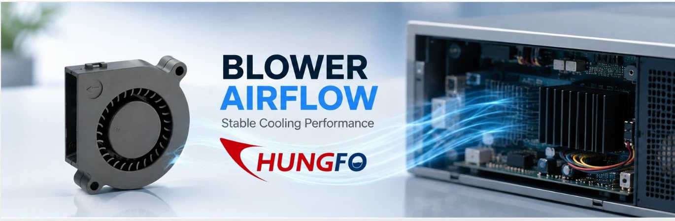
例えば、電子機器内部に設置された小型送風機を想像してみてください。空気は吸気口から入り、送風機を通過し、狭い内部通路を通り、ヒートシンクを通過し、小さな通気口から排出されます。
それぞれの部分が抵抗を生み出す。
空気の流れ経路が比較的開放的であれば、送風機は適切な風量で安定した状態で動作することができる。
出口が狭くなると、システム抵抗が増加する。
フィルターが汚れると、抵抗値は再び上昇する。
ヒートシンクに埃が付着すると、抵抗値がさらに上昇する可能性があります。
最終的には、送風機は動作範囲のうち、風量が非常に少なくなり、空力特性が不安定になる領域に追い込まれる可能性がある。
送風機の設計やシステム構成によっては、気流の脈動、圧力変動、騒音の変化、振動、その他の不安定な挙動が生じる可能性があります。
したがって、エンジニアは送風機のサージング現象を単に送風機モーター内部の問題と考えるべきではない。
これは通常、送風機と空気の流れシステム全体との相互作用の結果である。
小型送風機で送風速度の急激な変化(サージング)はよくあることですか?
これは機器設計者にとって重要な問題である。
小型遠心送風機は空力不安定性を起こす可能性があるが、エンジニアは小型送風機の用途に「サージング」という用語を適用する際には注意する必要がある。
大型の産業用遠心圧縮機や大型のプロセスブロワーでは、大きな流量逆転や圧力変動を伴う強いサージ状態が発生する可能性があります。電子機器や家電製品の冷却に使用される小型の直流ブロワーは、一般的に流量がはるかに低く、システム容量も小さいため、より低速で動作します。
その結果、症状はしばしば異なる。
小型送風機では、以下のような現象が発生する可能性があります。
空気の流れが減少
より高い静圧
脈動する気流
空力騒音の変化
振動の増加
変動するモーター負荷
冷却性能の低下
これらの状況は、従来の産業的な意味での深刻なサージではない場合でも、過剰なシステム抵抗によって引き起こされる可能性があります。
したがって、マーケティングや技術コミュニケーションにおいては、小型遠心送風機は、好ましくないシステム条件下では、不安定な気流やサージのような挙動を示す可能性があると説明する方がより正確である。
この区別によって、技術的な議論の信憑性が高まる。
また、送風機を選ぶ際には、単に風量定格が最も高い製品を探すだけでは不十分であることを顧客に理解してもらうのにも役立ちます。
システム抵抗がなぜそれほど重要なのか
システム抵抗は、小型遠心送風機の実際の性能に影響を与える最も重要な要因の一つである。
送風機の仕様書には最大風量値が記載されている場合があります。しかし、最大風量は一般的に特定の試験条件下で測定されたものであり、送風機がほとんど抵抗を受けない状況で発生する可能性があります。
実際の機器は異なる。
送風機が設置されたら、空気は空気流路全体を通って流れる必要があります。
フィルターは抵抗を生み出す。
グリルは抵抗を生み出す。
ヒートシンクは抵抗を生み出す。
狭い管路は抵抗を生み出す。
長いダクトは抵抗を生み出す。
急な曲がり角は抵抗を生み出す。
小さなコンセントは抵抗を生み出す。
それらの複合的な影響は、重大なものとなり得る。
このため、エンジニアは最大風量だけを考慮するのではなく、風量と静圧の関係に着目すべきである。
例えば、高い自由空気流量を謳っている送風機でも、密度の高い冷却構造物に接続すると、実際に供給される風量は著しく減少する可能性がある。
これは特に小型機器において重要です。なぜなら、設計者は空気通路のためのスペースが限られていることが多いからです。
利用可能な空気流路が狭くなると、圧力損失は急速に増加する可能性がある。
システム抵抗が高くなりすぎると、送風機は運転時間のほとんどを低風量・高圧の状態で過ごすことになる可能性がある。
これにより冷却性能が低下し、不安定な空力特性が生じる可能性があります。
自由空気流量と実際の運転流量の違い
送風機の選定において最もよくある間違いの一つは、自由空気流量の値だけを比較することです。
自由空気流とは、外部からの空気抵抗が最小限の状態を指します。
実際の機器は、完全に制約のない条件下で稼働することはほとんどない。
送風機を使ってヒートシンクに空気を送り込む冷却用途を考えてみましょう。
ヒートシンクのフィン間隔が狭い場合、空気抵抗が大きくなる可能性があります。
次に、ダストフィルターを取り付けます。
次に、細いコンセントを取り付けます。
次に、空気通路に2つの曲がり角を追加します。
最終的なシステム抵抗は、当初の計算結果よりもはるかに高くなる可能性がある。
送風機は、これらの圧力損失すべてを克服しなければならない。
したがって、実際の空気流量は、自由空気条件下で表示される数値よりもはるかに低くなる可能性があります。
そのため、プロ仕様の送風機を選定する際には、常に想定されるシステム圧力を考慮する必要があります。
小型遠心送風機で不安定な気流が発生する原因は何ですか?
不安定な気流には、いくつかの要因が関与している可能性がある。
一つ目は、出口の制限が過度であることです。
排気口が小さすぎると、送風機はシステムを通して空気を送るために、より高い圧力を発生させる必要がある。
2つ目は、空気通路のサイズが小さすぎることです。
狭い通路は空気の速度と圧力損失を増加させる。
3つ目は、フィルター抵抗が過剰であることです。
埃が溜まると、フィルターのろ過性能はさらに低下する。
4つ目は、吸気口の設計不良です。
A blower needs a suitable air supply. If the inlet is partially blocked or airflow enters the impeller unevenly, aerodynamic performance may deteriorate.
The fifth is excessive duct bending.
Sharp bends close to the blower can create turbulence and uneven velocity distribution.
The sixth is improper blower selection.
A blower that is too small may not have sufficient pressure capability for the application.
A blower that is too large may create excessive pressure and force the system to use restrictive control methods.
The seventh is changing operating conditions.
A system may work well during initial testing but become less stable after filters become dirty or when equipment configuration changes.
Why Small Blower Size Does Not Mean Simple Airflow Design
Because small blowers occupy very little physical space, designers sometimes assume that airflow design is also simple.
In reality, compact systems can be more challenging.
A large industrial ventilation system may have sufficient space for smooth ducts, gradual transitions, large filters, and appropriately sized outlets.
A compact electronic device may have only a few centimeters of available space.
The designer may need to route air around circuit boards, heat sinks, batteries, cables, brackets, and structural components.
This creates many local restrictions.
A blower may have excellent performance when tested alone, but the same blower can perform very differently after installation.
Therefore, compact blower applications require careful attention to the complete airflow path.
How To Recognize Potential Blower Instability
Engineers and maintenance personnel can look for several warning signs.
The first is unusual airflow fluctuation.
If the equipment operates under a stable thermal load but airflow repeatedly changes, the airflow path should be inspected.
The second is pressure fluctuation.
A pressure sensor can help identify changes in system pressure that may not be obvious from airflow measurements alone.
The third is unusual noise.
A small blower operating normally should produce relatively consistent aerodynamic noise. Pulsating or changing noise can indicate turbulence, excessive restriction, or unstable airflow.
The fourth is increased vibration.
Aerodynamic instability can create changing forces on the impeller and housing.
The fifth is reduced cooling performance.
If electronic components become hotter even though blower speed has not changed, system resistance or airflow restriction may have increased.
The sixth is changing motor current.
Changes in aerodynamic loading can affect the electrical load of the motor.
These symptoms should be evaluated together rather than individually.
Does Higher RPM Always Solve The Problem?
Increasing blower speed can increase airflow and pressure, but it should not automatically be treated as the solution.
Suppose a filter is becoming blocked.
The equipment begins to experience reduced airflow.
An operator increases blower speed.
Airflow improves temporarily.
However, the filter remains blocked.
The blower now operates at a higher speed and may consume more power while generating higher pressure.
If the system resistance continues increasing, the operating condition may eventually become unfavorable again.
Therefore, higher speed can compensate for some operating changes, but it cannot replace proper airflow-path design and maintenance.
Engineers should always determine why airflow is declining before simply increasing speed.
Selecting The Right Blower Performance
For small centrifugal blowers, the most important selection information includes airflow, static pressure, operating voltage, speed, noise, dimensions, power consumption, operating temperature, and expected service life.
Among these parameters, the airflow-pressure relationship is particularly important.
The required operating point should be identified first.
For example, if the equipment requires a certain airflow while overcoming a defined static pressure, the selected blower should be able to provide that combination under the actual operating conditions.
This is much more meaningful than selecting a blower simply because its maximum airflow is higher than the required value.
Engineers should also consider the operating range.
If the equipment can experience changes in filter condition, temperature, valve position, or airflow demand, the blower should maintain acceptable performance across those conditions.
40mm Blower FanApplications And Airflow Stability
A 40mm blower fan is typically associated with compact equipment where installation space is limited.
Such small blowers can be useful for localized cooling inside electronic devices, control systems, instruments, communication equipment, and other compact assemblies.
However, their small size means that the airflow path can have a relatively large influence on total system resistance.
A small outlet that appears acceptable visually may represent a significant restriction relative to the blower's available airflow area.
Likewise, a narrow internal channel may consume a large portion of the available pressure.
Therefore, when designing a system around a 40mm blower fan, engineers should evaluate the complete airflow path rather than only the blower itself.
The inlet area, outlet area, duct length, bends, filters, and heat dissipation components should all be considered.
100mm Blower FanApplications
A 100mm blower fan provides more installation flexibility than extremely compact blowers in some applications and may be selected when greater airflow or pressure capability is required.
However, larger physical size does not automatically eliminate airflow instability.
A 100mm blower fan can still operate under excessive system resistance if the connected duct, filter, heat exchanger, or outlet is improperly designed.
The same selection principle therefore applies.
Engineers should match the blower to the actual system operating point.
The objective is stable airflow rather than simply maximum airflow.
Blower 5015And Compact Cooling Design
A blower 5015 is an example of the type of compact blower format that can be considered for space-constrained cooling applications.
When using compact blowers of this type, designers should pay particular attention to the relationship between blower dimensions and airflow-path dimensions.
A compact blower may fit easily into the equipment, but the surrounding structure can still restrict airflow.
For example, placing the blower directly against a narrow wall or mounting bracket may reduce the effective inlet area.
Similarly, connecting the outlet to a narrow passage may increase pressure loss.
These details can influence actual performance more than the nominal blower dimensions suggest.
How Inlet Design Affects Blower Performance
The blower inlet is often overlooked.
Air should be able to enter the blower smoothly and reasonably uniformly.
If the inlet opening is partially blocked, the blower may have to operate with an uneven velocity distribution.
A sharp bend immediately before the inlet can also create turbulence.
In compact equipment, engineers may need to position the blower close to other components because of space limitations.
However, leaving adequate inlet clearance can improve airflow quality.
The inlet grille should also provide sufficient open area.
A decorative grille may look attractive but create unnecessary pressure loss if its open area is too small.
How Outlet Design Affects System Resistance
The outlet is equally important.
A blower may generate sufficient pressure, but if the outlet cannot pass the required airflow, system resistance will increase.
The outlet should be appropriately sized.
Sudden contractions should be avoided where possible.
Sharp changes in direction should be minimized.
If a protective grille is required, its open area should be evaluated.
If a filter is installed at the outlet, its pressure drop should be included in the system calculation.
These small design decisions can have a significant effect on the final operating point.
Filters And Their Impact On Blower Operation
Filters are important for protecting equipment from dust, but they inevitably create pressure loss.
A new filter may have relatively low resistance.
After extended operation, dust accumulation can increase pressure drop.
This means the blower operating point can gradually change over time.
A cooling system that performed well during initial testing may therefore deliver less airflow several months later.
For equipment requiring stable thermal performance, filter condition should be included in the maintenance plan.
Engineers should also specify the acceptable filter pressure drop rather than treating filtration as an isolated component.
Heat Sinks Can Also Create Significant Resistance
Heat sinks are widely used in electronic cooling systems.
While a heat sink improves heat transfer, closely spaced fins can restrict airflow.
If the blower must force air through a dense fin structure, static pressure requirements increase.
The thermal engineer should therefore consider both heat transfer and pressure loss.
A heat sink with extremely dense fins may provide a large heat transfer surface but require more blower pressure.
A slightly different fin spacing may reduce pressure loss while still providing adequate thermal performance.
The best solution is usually a balance between thermal performance and airflow resistance.
The Importance Of System Testing
Calculations are important, but prototype testing is often necessary.
A small blower should ideally be tested inside the actual or representative equipment.
Testing should measure airflow, pressure, temperature, noise, vibration, and motor electrical parameters where appropriate.
The equipment should be tested under different thermal loads.
Minimum, normal, and maximum operating conditions should be evaluated.
If the system uses a filter, test both clean and representative loaded conditions when practical.
If the blower uses speed control, the complete control range should also be tested.
This approach allows engineers to identify problems before mass production.
How Engineers Can Reduce Surge Risk
The first step is to reduce unnecessary system resistance.
Use appropriately sized airflow channels.
Avoid unnecessary bends.
Provide adequate inlet and outlet areas.
Select filters with suitable pressure-drop characteristics.
Avoid excessive restrictions around heat sinks.
Choose the blower based on the actual airflow-pressure requirement.
Provide sufficient operating margin.
Use appropriate speed control when necessary.
Monitor system performance during operation.
Maintain filters and airflow paths.
These measures can significantly improve airflow stability.
Should Engineers Choose A Higher Pressure Blower?
Sometimes a higher pressure blower is appropriate.
If the system contains dense heat sinks, long ducts, filters, or other restrictive components, the blower needs enough pressure capability to maintain the required airflow.
However, selecting the highest pressure blower available is not always the best solution.
The blower should be matched to the system.
Too little pressure capability results in insufficient airflow.
Excessive pressure capability may increase noise, power consumption, and the need for restrictive control.
The correct solution is the blower that can provide the required airflow at the required static pressure while operating within a suitable region of its performance curve.
How Speed Control Can Help
Speed control can help compensate for changes in cooling demand.
When thermal load increases, blower speed can be increased within the permitted operating range.
When thermal load decreases, speed can be reduced.
This can improve energy efficiency and reduce unnecessary noise.
However, the control system should have defined operating limits.
It should not continuously command the blower into an unstable region.
For critical equipment, pressure or airflow feedback can be used to improve control accuracy.
The Role Of Motor And Impeller Design
Although system resistance is extremely important, blower construction also influences stability.
Impeller geometry determines how air is accelerated and pressurized.
Housing geometry affects the airflow path.
Motor speed affects pressure and airflow capability.
Impeller balance affects vibration.
Bearing quality influences mechanical reliability.
Material selection affects temperature resistance and structural stability.
Therefore, engineers should consider both aerodynamic performance and mechanical design when evaluating a blower.
Why Noise Can Be An Early Warning Sign
Noise is often one of the first things that users notice.
A change in sound may indicate increased turbulence or unstable airflow.
For compact equipment, noise is particularly important because users may be close to the product.
If a blower becomes noticeably louder after installation, engineers should check whether the airflow path is causing excessive pressure loss.
The noise may not be caused by the blower itself.
A narrow outlet, grille, duct bend, or turbulent transition can create significant additional aerodynamic noise.
Why Vibration Should Not Be Ignored
Vibration in a small blower can have several causes.
Mechanical imbalance is one possibility.
Bearing problems are another.
Improper mounting can also increase vibration.
However, aerodynamic instability should also be considered.
If vibration increases together with airflow fluctuation and changing noise, the system should be evaluated as a whole.
Replacing the blower without correcting the airflow restriction may not solve the problem.
Designing For Long-Term Reliability
A blower that performs well on the first day should continue performing well months or years later.
Long-term reliability requires consideration of dust accumulation, temperature, filter loading, component aging, changing operating conditions, and maintenance access.
The airflow system should therefore be designed with maintenance in mind.
Filters should be accessible.
Air channels should not be unnecessarily narrow.
Critical components should not be placed directly in front of the inlet.
Cleaning should be practical.
Sensors should be positioned where they can provide useful information.
These design details can significantly improve the long-term stability of the cooling system.
A Practical Troubleshooting Process
When a small blower system begins showing unstable airflow, engineers can follow a structured troubleshooting process.
First, confirm whether the required airflow and thermal load have changed.
Second, inspect the inlet.
Third, inspect the outlet.
Fourth, check filters and grilles.
Fifth, inspect heat sinks and ducts.
Sixth, measure static pressure.
Seventh, measure actual airflow.
Eighth, compare the measured operating point with the blower performance curve.
Ninth, check motor speed and electrical current.
Tenth, inspect mounting, vibration, and mechanical condition.
This process is more reliable than immediately replacing the blower.
Working With A Professional Blower Manufacturer
For equipment manufacturers, early communication with the blower supplier can simplify product development.
Instead of providing only the desired blower dimensions, engineers should provide the actual application requirements.
Useful information includes required airflow, estimated static pressure, operating voltage, available installation space, operating temperature, noise requirements, expected operating hours, and environmental conditions.
The blower manufacturer can then recommend a suitable performance range.
For customized applications, prototype testing can further improve confidence.
This approach can help prevent the common problem of selecting a blower according to dimensions first and discovering later that the actual airflow is insufficient.
China Chungfo Fan And Small Blower Applications
Chungfo Fanfocuses on the development and production of cooling fans, centrifugal blowers, axial fans, cross-flow fans, and other air-moving products for different equipment applications.
For compact blower applications, the selection process should begin with the complete airflow requirement rather than a single dimensional parameter.
Airflow, static pressure, voltage, speed, noise, operating temperature, installation conditions, and expected service life all need to be considered.
This application-oriented approach is especially important when a small blower is installed in a compact enclosure.
The blower itself may occupy only a small area, but the surrounding airflow structure can strongly influence its actual performance.
By evaluating the complete system, engineers can better balance cooling performance, energy consumption, noise, installation space, and reliability.
Final Thoughts
Small centrifugal blowers are highly useful for compact cooling and ventilation applications, but their performance depends strongly on the system in which they are installed.
Blower surging in the classical industrial sense is not necessarily the most common problem for small electronic or appliance blowers. However, unstable airflow, high system resistance, pressure fluctuation, pulsating noise, vibration, and significant airflow reduction are all important issues that engineers should understand.
The key lesson is that maximum airflow is not enough for blower selection.
The real operating point depends on both the blower and the system.
A small blower connected to a restrictive airflow path may deliver much less airflow than expected. Increasing speed may temporarily compensate for the problem, but it does not eliminate the underlying resistance.
Engineers should therefore evaluate the complete airflow path, including the inlet, outlet, filters, ducts, heat sinks, grilles, bends, and other components.
The blower should be selected according to the required airflow and static pressure, and the system should be validated under realistic operating conditions.
For compact applications using products such as a 40mm blower fan, a 100mm blower fan, or a blower 5015, careful system design is particularly important because limited installation space can create significant airflow restrictions.
Ultimately, stable blower operation comes from matching the blower to the real system rather than simply selecting the largest airflow specification.
When blower selection, airflow-path design, testing, control, and maintenance are considered together, engineers can achieve more reliable cooling performance, lower unnecessary noise, better energy efficiency, and longer equipment life.
FAQ
What is blower surging?
Blower surging is an unstable airflow condition in which pressure and airflow fluctuate instead of remaining relatively stable. In small blower applications, engineers may more commonly encounter airflow instability caused by excessive system resistance.
Can a small centrifugal blower experience surge?
Yes, small centrifugal blowers can experience aerodynamic instability under unfavorable operating conditions. However, the behavior is often less severe than the classical surge phenomenon associated with large industrial centrifugal machines.
What usually causes unstable airflow in a small blower system?
Common causes include excessive outlet restriction, narrow ducts, dirty filters, dense heat sinks, poor inlet design, sharp bends, improper blower selection, and changing operating conditions.
Does a higher RPM always solve low airflow?
No. Increasing speed can increase airflow and pressure, but it cannot remove a blocked filter, undersized duct, or restricted outlet. The underlying system resistance should be investigated first.
Why is static pressure important for small blower selection?
Static pressure indicates how much resistance the blower must overcome. A blower with a high free-air airflow rating may provide much less actual airflow when connected to a restrictive system.
Can a 40mm blower fan be used for high-resistance applications?
It can be used when its performance curve provides sufficient airflow at the required static pressure. The compact size alone does not determine whether it is suitable.
Is a 100mm blower fan automatically more stable?
Not necessarily. A larger blower may provide greater airflow or pressure capability, but stability still depends on the relationship between the blower and the connected airflow system.
What should engineers check when blower noise suddenly increases?
They should inspect the inlet, outlet, filters, ducts, grilles, heat sinks, mounting structure, and operating point. Increased noise may result from turbulence or excessive system resistance rather than a defective blower.
Can a blower 5015 be used in compact electronic equipment?
Compact blower formats can be suitable for electronic equipment when their airflow and pressure characteristics match the application's requirements. Engineers should evaluate the complete airflow path before final selection.
How can engineers reduce the risk of unstable airflow?
Engineers can reduce unnecessary system resistance, provide adequate inlet and outlet areas, select suitable filters, design smoother airflow paths, choose the blower according to the required airflow and static pressure, and validate the system under realistic operating conditions.
Should a blower always be selected with the highest possible airflow?
No. Maximum airflow is only one parameter. The blower should provide the required airflow at the actual system static pressure while operating within an appropriate and stable range.
Can dirty filters affect blower performance?
はい。埃が溜まるとフィルターの抵抗が増加し、風量が低下したり、送風機の作動点が変わったりする可能性があります。安定した性能を維持するためには、定期的な点検と交換が重要です。
設置後に送風機の性能テストを行うべき理由は何ですか?
実際の機器は、自由空間での試験時には存在しない抵抗を生み出す可能性があるためです。設置条件によって、気流、圧力、騒音、温度、消費電力が大きく変化する可能性があります。
送風機の推奨を依頼する際、エンジニアはどのような情報を提供すべきでしょうか?
重要な情報には、必要な風量、静圧、動作電圧、設置寸法、動作温度、騒音要件、デューティサイクル、環境条件、および予想される耐用年数が含まれます。
小型遠心送風機を選定する際に最も重要な原則は何ですか?
最も重要な原則は、製品の物理的なサイズや最大風量だけに基づいて製品を選択するのではなく、送風機の風量と圧力性能を実際のシステム動作点に合わせることです。